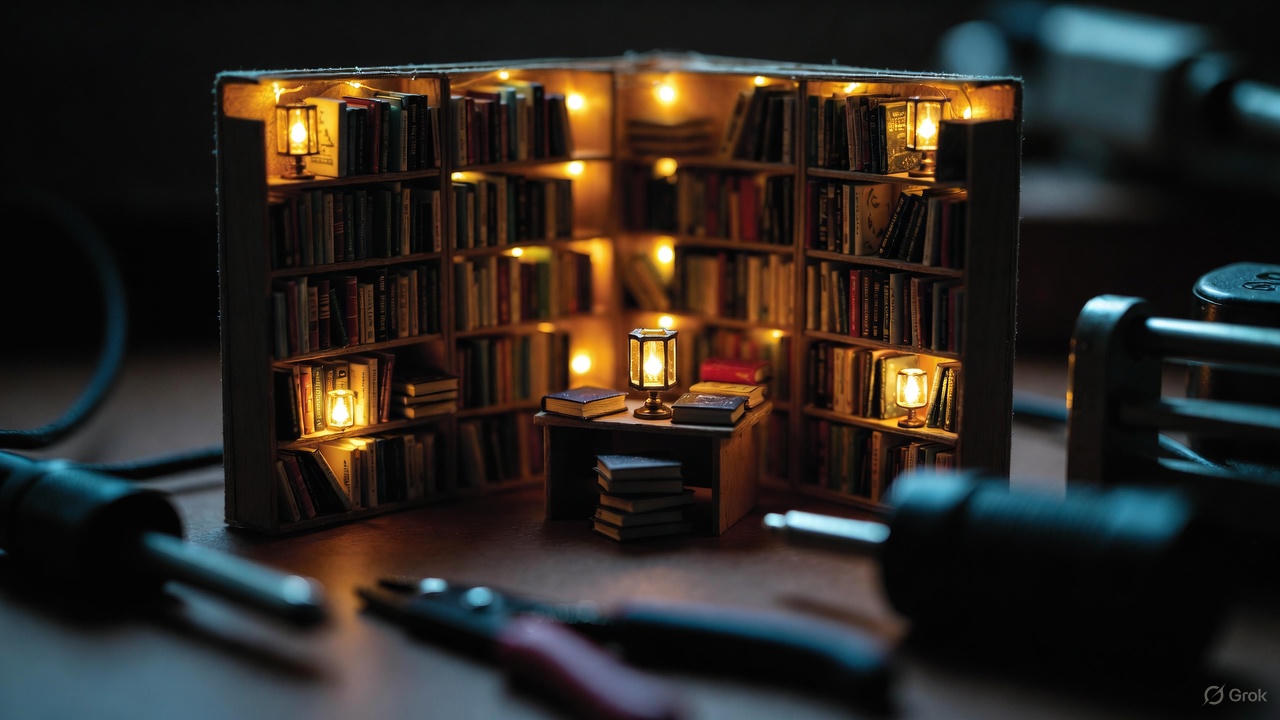
The transformative moment when you activate lighting in a completed miniature diorama—watching warm illumination bring a meticulously constructed book nook or café scene to life—represents the culmination of dozens of hours of detailed assembly work.
Yet for many builders, particularly those new to miniature construction, the electrical component installation process generates significant anxiety and frequently results in visible wiring, non-functional circuits, or compromised aesthetic presentation.
After fifteen years constructing over 300 illuminated miniature dioramas and assisting countless builders through electrical troubleshooting, I've developed systematic approaches to LED installation that eliminate common failure points while maintaining the visual integrity that makes miniature scenes compelling.
This comprehensive guide provides the technical knowledge, practical techniques, and professional-grade strategies necessary to achieve seamless lighting integration in book nooks and miniature room boxes.
Understanding Miniature Lighting Systems: Technical Fundamentals.
Before addressing installation methodology, understanding the electrical principles governing miniature lighting systems prevents common errors and enables informed component selection.
LED Technology in Miniature Applications.
Modern miniature kits exclusively employ Light Emitting Diodes (LEDs) rather than incandescent bulbs for several compelling reasons:
Power efficiency: LEDs convert approximately 80-90% of electrical energy into light, versus 20% for incandescent bulbs. This efficiency translates to:
- Extended battery life (6-20× longer depending on capacity)
- Minimal heat generation (critical in enclosed spaces with flammable materials)
- Lower power consumption enabling multiple light operation from small batteries
Longevity: Quality LEDs maintain 70%+ brightness for 25,000-50,000 hours of continuous operation—effectively permanent for display applications involving several hours of daily illumination.
Size advantages: Miniature LEDs measure 2mm-5mm in diameter, enabling realistic lamp installations and concealed accent lighting impossible with larger incandescent bulbs.
Voltage compatibility: LEDs operate efficiently on low voltage DC power (1.5V-12V), making them inherently safe and compatible with coin cell batteries, AA batteries, or USB power adapters.
The Two Primary LED Configuration Types
Miniature lighting systems employ two distinct LED arrangements, each offering specific advantages and limitations:
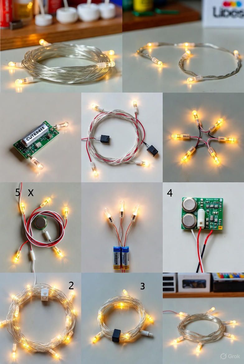
Configuration 1: Copper Wire LED Strings (Integrated Systems)
Physical description: Ultra-thin copper wire (typically 30-32 AWG, approximately 0.25mm diameter) with surface-mount LEDs soldered at regular intervals. The wire flexibility allows routing through tight spaces and around corners without kinking.
Electrical characteristics:
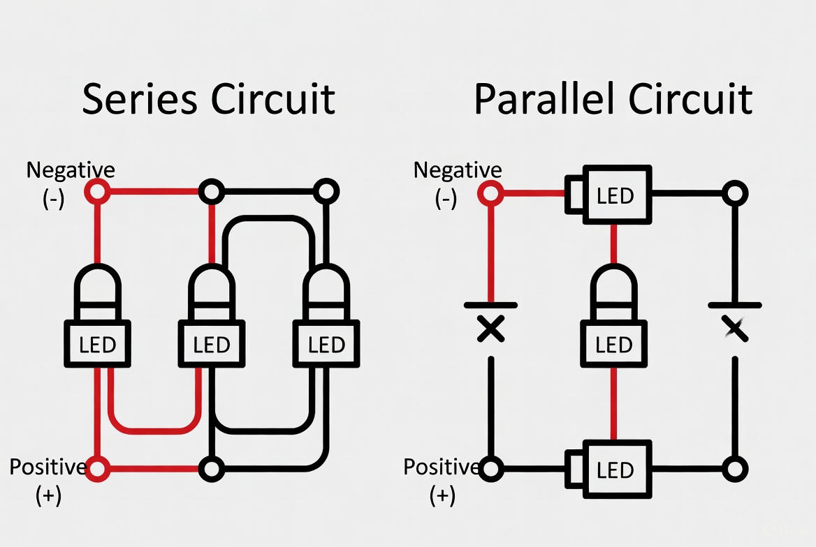
- Series circuit configuration: electrical current flows sequentially through all LEDs
- Typical specifications: 10-20 LEDs per string, 3V operation (two CR2032 coin cells or one CR2477)
- Fixed spacing: LEDs positioned at manufacturer-determined intervals (usually 10cm-15cm)
Advantages documented through extensive use:
- Minimal visual intrusion: the copper wire's thinness (comparable to sewing thread) makes concealment straightforward
- No soldering required: factory-installed LEDs eliminate technical skill barriers
- Flexible routing: wire bends easily around obstacles and furniture
- Even illumination distribution: multiple LEDs create ambient lighting rather than point sources
Limitations encountered in practice:
- Series circuit vulnerability: component failure at any point interrupts the entire circuit
- Fixed length constraints: trimming the wire typically eliminates LEDs (cutting between LEDs leaves non-functional components)
- Limited positioning control: LED placement determined by factory spacing rather than design requirements
- Copper wire visibility: while thin, bare copper wire remains visible unless properly concealed
Configuration 2: Individual Pre-Wired LEDs (Modular Systems)
Physical description: Discrete LED components with attached wire leads (one red/positive, one black/negative), typically using 28-30 AWG stranded wire.
LED diameter ranges from 3mm (standard) to 5mm (wide-angle), with color temperatures from 2700K (warm white) to 6500K (cool white).
Electrical characteristics:
- Parallel circuit capability: each LED connects independently to power source
- Typical specifications: 3mm diameter, 20mA current draw, 2.8-3.2V forward voltage
- Variable wire length: leads can be extended or shortened as needed
Advantages from professional installation experience:
- Precise positioning control: LEDs install exactly where illumination is required
- Selective operation: individual LEDs can be switched independently
- Failure isolation: single LED malfunction doesn't affect other circuit components
- Customizable brightness: different LED types can be mixed based on illumination requirements
Limitations requiring consideration:
- Technical skill requirements: connecting multiple LEDs demands basic soldering or wire-twisting competency
- Increased wire volume: separate leads for each LED create more material requiring concealment
- Planning complexity: circuit design requires determining power distribution and switch placement
- Higher component cost: individual LEDs with leads cost more per unit than integrated strings
Selecting the Appropriate System for Your Project.
Choose copper wire LED strings when:
- Building pre-designed kits with included lighting (Rolife, Robotime, Cutebee)
- Creating ambient general illumination throughout a space
- Minimizing technical complexity for a first lighting project
- Working with limited concealment opportunities (the thin wire is easiest to hide)
Choose individual pre-wired LEDs when:
- Designing custom lighting schemes with specific fixture placement
- Installing lights within miniature lamps, lanterns, or chandeliers
- Creating accent lighting highlighting particular features
- Building advanced projects where circuit control and modification flexibility matters
Essential Tools and Materials for Professional Installation.
Successful LED installation requires specific tools selected for working with delicate components in confined spaces. General-purpose household tools prove inadequate for miniature electrical work.
Primary Tools (Mandatory)
1. Wire strippers (precision micro-strippers) Standard wire strippers designed for 14-22 AWG household wiring cannot accommodate the 28-32 AWG wiring in miniature applications. Precision strippers feature:
- Adjustable jaws calibrating to specific wire gauges
- Fine-point tips accessing tight spaces
- Minimal grip pressure requirement preventing wire damage
Specific recommendation based on testing: VETUS Tweezers ESD-15 Anti-Static or Xuron 9100 Micro-Shear Flush Cutters with built-in strippers handle miniature gauge wire without crushing delicate copper strands.
2. Electrical tape (professional grade) Quality electrical tape provides:
- Reliable insulation preventing short circuits
- Conformability wrapping around irregular shapes
- Adhesive longevity maintaining bond over years
Specification requirements: 3M Scotch Super 33+ vinyl electrical tape (not general-purpose tape) provides UL-listed electrical insulation suitable for low-voltage applications.
3. Double-sided tape (professional mounting tape) For securing wires to surfaces without creating visible bumps:
- Ultra-thin profile (under 0.5mm)
- Permanent adhesive that won't release over time
- Clean removal if repositioning becomes necessary
Recommendation: 3M VHB (Very High Bond) mounting tape in 1mm thickness or slimmer provides permanent wire adhesion without visible bulk.
4. Multimeter (voltage and continuity testing) Even basic multimeters provide critical diagnostic capabilities:
- Voltage measurement confirming battery condition
- Continuity testing identifying circuit breaks
- Resistance measurement evaluating connection quality
Entry-level recommendation: Any digital multimeter with continuity testing function (typically $10-15) proves adequate for miniature applications.
Supplementary Materials
Heat shrink tubing (for permanent connections): When properly applied, heat shrink tubing creates waterproof, insulated connections superior to electrical tape:
- Diameter: 2mm-3mm accommodates typical wire bundles
- Shrink ratio: 2:1 or 3:1 provides adequate coverage
- Application: slip over connection before joining wires, apply heat gun (or carefully applied lighter flame) to shrink
Cable management clips (micro-sized): Adhesive-backed clips (2mm-3mm width) secure wires along surfaces more reliably than tape alone, particularly for permanent installations.
Conductive adhesive or solder (advanced installations): For permanent, low-resistance connections, conductive adhesive (MG Chemicals 8331) or traditional soldering (using 60/40 rosin-core solder with 15-25W iron) creates superior joints compared to twisted wire connections.
Professional Wire Concealment Techniques.
The defining characteristic separating amateur from professional miniature lighting installations is wire visibility. Exposed wiring—regardless of how well the lighting functions—immediately undermines the immersive quality of miniature scenes.
Technique 1: Subsurface Wire Routing (The False Floor Method)
This approach conceals wiring beneath the visible floor surface, creating a hidden wire management layer.
Materials required:
- Thin basswood strips (2mm-3mm thickness, 5mm-8mm width)
- Wood glue (Aleene's Tacky Glue or Titebond)
- Decorative floor material (paper, thin wood veneer, or painted cardstock)
Installation process:
Step 1: Circuit planning Before installing any structural components, map wire routing paths from each LED location to the central power connection point (typically along room edges to minimize visible floor area consumption).
Step 2: Create wire channels Cut basswood strips to length and glue them to the base floor parallel to wire routing paths, spacing them 8mm-12mm apart. These strips create raised "rails" with valleys between them where wires will lay.
Critical detail: Leave a small gap (3mm-5mm) at corners where strips meet to allow wires to transition between channels.
Step 3: Route wiring Lay wires within the channels created by raised strips. Use small dots of glue every 15mm-20mm to secure wires, preventing them from shifting during subsequent construction.
Step 4: Apply finish floor Once wiring is secured and tested (always test before covering—correction becomes nearly impossible afterward), glue the decorative floor material over the entire surface, concealing both strips and wires.
Effectiveness: This technique completely eliminates wire visibility, though it does raise the floor level by 2-3mm (insignificant in most designs but potentially affecting doorway clearances in some kits).
Technique 2: Vertical Corner Concealment
For wires that must travel vertically (from floor to ceiling fixtures, for example), corner routing provides the least visible placement.
Implementation:
Step 1: Select optimal corner Choose the rear corner most distant from primary viewing angles. Miniatures are typically viewed from the front, making rear corners the best concealment locations.
Step 2: Secure wire with minimal adhesive Apply tiny dots of tacky glue (use a toothpick for precision) at 20mm intervals along the wire's length. Press wire firmly into the corner joint, ensuring it sits in the 90-degree angle where walls meet.
Step 3: Camouflage integration After glue dries, apply matching paint directly over the wire. Use a fine brush (size 00 or 000) and apply 2-3 thin coats rather than one thick coat. The wire essentially becomes part of the corner shadow, rendering it nearly invisible.
Enhancement technique: For dark-colored wires in light-colored rooms, apply a coat of light-colored primer before the final paint color. This prevents the dark wire from showing through.
Technique 3: Decorative Concealment (Botanical Cover Method)
When wires must cross open spaces where subsurface routing or corner placement is impossible, decorative elements can transform necessary wires into design features.
Materials:
- Dried reindeer moss, static grass, or paper foliage
- Fine-gauge floral wire or thread (for training climbing plants)
- Tacky glue or hot glue (low-temp setting)
Application:
Step 1: Establish planting points Identify anchor points at wire start and end locations where plants would logically grow (window boxes, floor planters, wall-mounted pots).
Step 2: Create trailing growth pattern Apply small pieces of moss or paper leaves along the wire's path, gradually building up coverage. Work from anchor points toward the center, creating the appearance of natural plant growth rather than uniform coverage.
Step 3: Integrate wire into design The wire should appear to be supporting climbing vegetation rather than being hidden by it. This subtle distinction makes the difference between "covering a mistake" and "intentional design element."
Example from my portfolio: In a Victorian conservatory build, power wires to overhead lighting became support structures for paper ivy, transforming a technical necessity into a key aesthetic element that enhanced rather than detracted from the design.
Technique 4: Structural Integration (Advanced)
For custom builds rather than kit assembly, designing wire management into the structure from the beginning provides the cleanest results.
Design principles:
- Hollow columns and posts: Use tubular components (brass or wood tubing) for structural elements, routing wires through the interior
- Baseboard channels: Create recessed channels behind baseboards and crown molding where wires can run concealed
- Removable panels: Design access panels (doors, removable wall sections) that allow wire routing behind surfaces while maintaining access for maintenance
This approach requires advanced planning and construction skills but produces the most professional results, particularly for permanent installations or pieces intended for sale or exhibition.
Power Source Options: Batteries vs. USB Conversion
The power source decision significantly impacts both convenience and maintenance requirements for illuminated miniatures.
Battery Power: Traditional Approach
Common battery types in miniature kits:
CR2032 coin cells (3V, 220mAh):
- Diameter: 20mm, Thickness: 3.2mm
- Typical runtime: 6-12 hours continuous use
- Advantages: Extremely compact, easy to conceal
- Disadvantages: Short runtime, relatively expensive per hour of operation
CR2450 coin cells (3V, 620mAh):
- Diameter: 24mm, Thickness: 5mm
- Typical runtime: 18-36 hours
- Advantages: Better capacity while remaining compact
- Disadvantages: Still limited runtime for frequent display use
AA alkaline batteries (1.5V each, 2500-3000mAh):
- Used in pairs or triple packs for 3V-4.5V operation
- Typical runtime: 40-80 hours with standard LED loads
- Advantages: Extended runtime, economical cost per hour
- Disadvantages: Larger battery holder requiring more concealment space
Performance optimization techniques:
- Lithium primary batteries: Lithium AA batteries (Energizer Ultimate Lithium) provide 3300mAh capacity versus 2850mAh for alkaline, extending runtime 15-20%
- Voltage regulation: Simple voltage regulator circuits prevent brightness decline as batteries discharge
- Efficient LED selection: Modern high-efficiency LEDs (120+ lumens per watt) reduce power consumption 40-50% compared to older technology
USB Power Conversion: Permanent Installation Solution
Converting battery-powered miniatures to USB operation eliminates ongoing battery costs while enabling continuous operation for display pieces.
Required components:
- USB cable with appropriate voltage output (5V standard USB)
- If kit operates at 3V: voltage step-down module (5V to 3V DC-DC converter, widely available for $2-4)
- Wire connectors or soldering supplies
Conversion process:
Step 1: Voltage requirement verification Measure existing battery voltage with multimeter:
- Two CR2032 cells = 6V
- Three AA cells = 4.5V
- Verify LED specifications (typically 2.8V-3.2V forward voltage)
Step 2: Select appropriate converter If USB's 5V output doesn't match your requirement:
- For 3V systems: LM2596 DC-DC buck converter module (adjustable output)
- For 6V systems: Direct USB power may work, though slight over-voltage (5V vs 6V) reduces LED lifespan marginally
Step 3: Connection Remove battery holder. Connect USB power module output (typically red/black wires) to the circuit's power input points (where battery terminals connected):
- Red (positive) to positive
- Black (negative/ground) to negative
Step 4: Secure and test Insulate all connections with electrical tape or heat shrink tubing. Test operation before final installation. Secure converter module in hidden location within the diorama.
Long-term cost analysis: A miniature display operated 4 hours daily requires approximately 120 hours monthly operation.
Battery cost:
- CR2032 cells (12-hour runtime) = 10 cells monthly at $0.50 each = $5.00/month
- Annual cost: $60
USB power cost:
- Conversion kit: $6 one-time cost
- Electricity (5V at 100mA = 0.5W × 120hrs/month = 60Wh = 0.06kWh at $0.12/kWh) = $0.007/month
- Annual cost: $6.08
The USB conversion pays for itself within 6-8 weeks of regular use.
Troubleshooting Common Lighting Problems.
Despite careful installation, lighting systems occasionally malfunction. Systematic diagnosis identifies issues efficiently.
Issue 1: Complete Circuit Failure (No Illumination)
Diagnostic sequence:
Check 1: Power source verification Measure battery voltage with multimeter. Batteries showing less than 70% of rated voltage (2.1V for 3V systems, 3.1V for 4.5V systems) may be insufficient despite appearing functional.
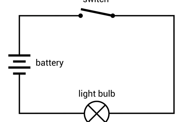
Check 2: Switch operation Many issues stem from faulty switches. Bypass the switch temporarily by connecting wires directly—if lights function, replace the switch.
Check 3: Connection integrity Inspect all wire junctions for:
- Loose connections (pull gently on each wire)
- Corrosion (white/green deposits on copper)
- Damage from movement or assembly stress
Check 4: LED polarity LEDs function only when connected with correct polarity (positive to positive, negative to negative). Reversed polarity prevents operation without damaging the component.
Issue 2: Intermittent Flickering
Common causes and solutions:
Cause 1: Loose connection Flickering during movement or vibration indicates inadequate wire connection. Solution: Re-strip wires and create tighter twisted connections, or preferably solder joints.
Cause 2: Inadequate battery contact Battery holders can develop poor contact through corrosion or spring weakness. Clean contacts with isopropyl alcohol and slightly bend spring contacts for improved pressure.
Cause 3: Wire damage Copper wire can break internally while insulation remains intact. This creates intermittent contact. Test by gently flexing the wire near connection points while monitoring operation—flickering during flexing confirms internal break.
Issue 3: Dim Illumination
Diagnostic considerations:
Voltage drop: Excessive wire length or thin gauge wire causes voltage drop between power source and LEDs. Calculate voltage drop:
Voltage Drop = Current (A) × Resistance (Ω)
For 30AWG copper wire: approximately 0.34Ω per meter
A 50cm wire run carrying 20mA (0.02A): 0.17Ω × 0.02A = 0.0034V drop (negligible)
However, multiple LEDs in series increase current, and very long runs accumulate significant resistance.
Solution: Use heavier gauge wire (28AWG instead of 30AWG) for long runs, or switch to parallel wiring configuration.
Excessive load: Adding more LEDs than the power source can adequately supply causes dimming. Each LED draws approximately 20mA. A CR2032 battery (220mAh capacity) can theoretically supply 220mA for one hour, but practical current draw should stay under 60-80mA for reasonable runtime.
Solution: Reduce number of LEDs or upgrade to higher-capacity power source.
Conclusion: Achieving Professional Lighting Integration
Mastering miniature lighting installation transforms static dioramas into dynamic, immersive scenes that command attention and convey the meticulous craftsmanship invested in construction. The techniques presented in this guide—from fundamental LED system understanding through advanced wire concealment strategies and USB power conversion—provide the comprehensive knowledge base necessary for professional-quality results.
The key insight differentiating successful lighting installations from problematic ones: proper planning before beginning assembly. Once structures are permanently glued and enclosed, correcting lighting issues becomes exponentially more difficult. Investing time in wire routing planning, testing circuits before concealment, and implementing proper connection techniques prevents the frustration of discovering problems after completion when correction options are limited.
As you implement these techniques across multiple projects, the process becomes increasingly intuitive. Circuit planning transitions from conscious effort to automatic consideration during design phases. Wire concealment opportunities become immediately apparent. Troubleshooting evolves from mystery to systematic diagnosis.
That transformative moment when you activate lighting in a completed build—watching warm illumination reveal intricate details and create atmosphere—justifies the technical attention invested in proper installation. The absence of visible wiring, reliable operation, and professional presentation quality elevate your work from hobby project to genuine craftsmanship.
Now apply these principles to your current project. Plan your wire routing. Select appropriate components. Execute concealment techniques carefully. Test thoroughly before final assembly. The glowing result will demonstrate your evolved technical competency while creating the magical illuminated miniature scene that inspired your initial interest in this rewarding craft.
Read Also: 5 Beginner Tips for Building Your First Miniature Kit.
